

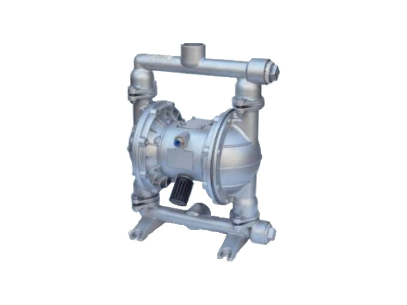
Compact, energy-efficient, corrosion-resistant, and perfect for chemical transfer is the QBK Leak-Free Pneumatic Diaphragm Pump. Low maintenance, no leaks, and resilience in challenging conditions.
Item No :
QBKOrder(MOQ) :
1Payment :
L/C T/T Alipay westernunion paypalProduct Origin :
ChinaColor :
CustomizedShipping Port :
shanghai shenzhen guangzhouLead Time :
please contact 504893184@qq.com or CP +8613696510409Package :
CustomizedMaterial :
Cast iron/Stainless steel/Fluorine-linedWorking Temp :
-30 to 180 ℃Working Pressure :
2.5 MPaLeak-Free Pneumatic Diaphragm Pump
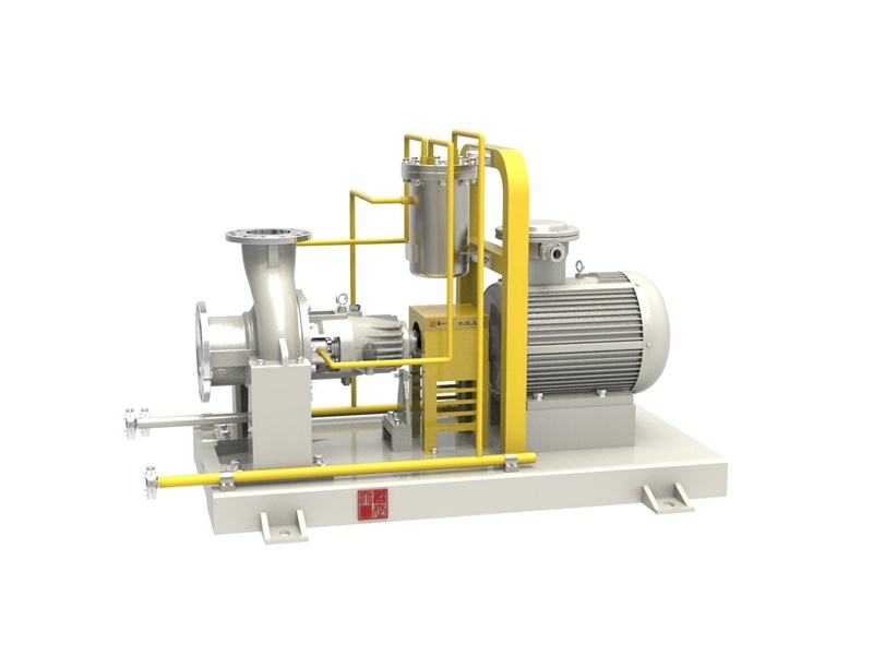
The QBK pneumatic diaphragm pump is designed to handle both free-flowing and highly viscous fluids with exceptional versatility. It combines the advantages of self-priming, submersible, canned motor, slurry, and trash pumps—requiring no priming and offering a suction lift of up to 7 m, a maximum head of 70 m, and an outlet pressure of ≥ 6 kgf/cm². Featuring a wide flow path that allows solids up to 10 mm with minimal wear, it ensures reliable performance across demanding applications. The air valve enables easy adjustment of flow rate and head (1–7 kgf/cm²), while its leak-free, explosion-proof air operation makes it suitable for hazardous chemical transfer. With submersible functionality, automatic dry-run and overload protection, and no moving parts in contact with the media, the pump offers low maintenance and long service life. Capable of handling viscosities up to 10,000 cP and operating without lubrication even during dry running, the QBK pump is an ideal choice for tough and critical industrial environments.
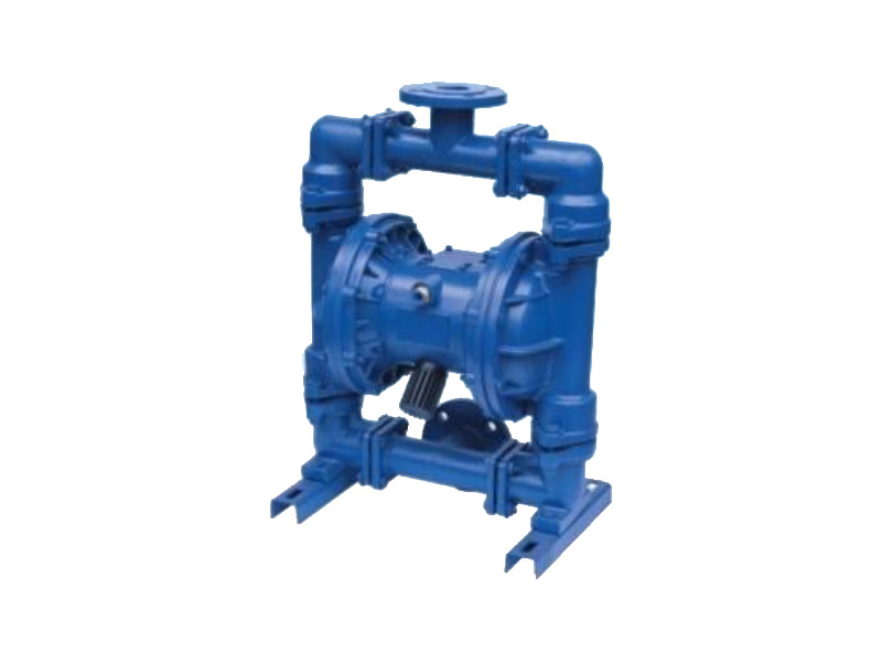
Main Applications
The QBK pneumatic diaphragm pump is a real workhorse in lots of businesses since it can move almost anything. I'm talking peanut butter, pickles, mashed potatoes, even sausages and chocolate! It also works with paints, coatings, ceramic glazes, and even bad stuff like corrosive or flammable liquids. It's also good for cleaning wastewater, moving cement, and dealing with very strong acids. Plus, this pump can even help push things through machines that separate solids from liquids.
Working Principle
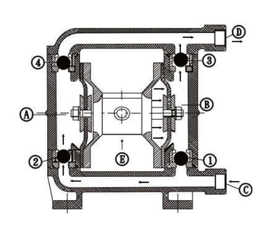
The QBK pneumatic diaphragm pump is divided into two pieces, which we will refer to as A and B. They have rod-connected diaphragms. Liquid is moved by air pushing one diaphragm while air is vented on the other side. The air valve flips to maintain fluid flow after a side is completed.
This is the summary:
1. When air enters, the right diaphragm is forced out.
2. Liquid is drawn in through the intake ③ when Section A expands. When liquid enters section ④, the ball valve ② opens, and valve ④ closes.
3. Squeezing simultaneously, section B uses ball valve ③ to force liquid out through outlet ①; valve ① closes to stop backflow.
4. You get a constant intake at ③ and output at ① as a result of this process continuously repeating.
Compact, energy-efficient, corrosion-resistant, and perfect for chemical transfer is the QBK Leak-Free Pneumatic Diaphragm Pump. Low maintenance, no leaks, and resilience in challenging conditions.
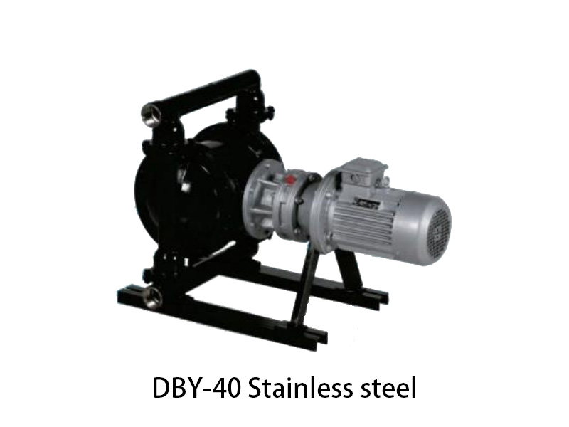
For industrial applications, the DBY New Type Electric Diaphragm Pump provides effective, leak-free fluid transmission with a robust design, low energy consumption, and silent operation.


 IPv6 network supported